SINGLE PHASE TRANSFORMER
INTRODUCTION
In modern world transformer has great importance because sometimes generation stations are very far away from the connected loads , so transmission line is needed to made a connection between power house and a connected load
as we the all the losses are due to current and the total power is equal to
so by increasing the value of voltage loses can be minimize , here where transfomer is needed to bring back these high voltage to the required voltages e.g (220v or 440v)
PRINCIPLE OF OPERATION
Transformer works on principle of electromagnetic induction,transformer is a static device which change voltage and current to different required levels but keeping the power constant
Transformer contain two coils , both are not connected electrically both coils connected magnetically through low reluctance path
The coil which is connected with a source is primary while the another one secondary coil
When Primary coil is connect with a source so flux will be generate and move towards secondary path through low reluctance path so according to Faraday's law emf will be generated in a secondary coil
PROPERTIES OF TRANSFORMER
- Frequency will be remain same
- EMF will be generated in a secondary coil
- Primary current depends on a secondary current
- voltage level will be changed according to requirement
- Transformer is also known as Ac generatot
TYPES OF TRANSFORMER
STEP UP VS>>VP
STEP DOWN VS<<VP
CONSTRUCTION OF A TRANSFORMER
- STEEL TANK
The body if a transformer is made of a steel,all parts of transformer is kept in a steel and the steel tank is filled with transformer oil used for insulation
2. CORE
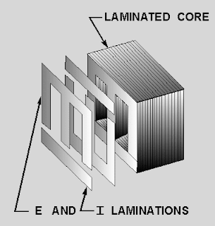
Core of a transformer is made of a laminated sheets so it can provide magnetic path and having less air gap , some times these sheets are kept in a heat to increase its permeability
These sheets are of size of 0.35 mm to 0.5 mm
All sheets are made of Silicon steel and all have high permeability
3.WINDING
In single phase their is 1 primary and 1 secondary winding while in three phase their are 3 primary and 3 secondary windings are there, they are connected according to requirement
Mostly the low voltage winding is place on core while the high voltage winding is place above low voltage winding , and their is proper insulation between them
4.CONSERVATOR
Conservator is a tank in a cylindrical shape ,connected through a pipe with transformer . A transformer of capacity higher than 1 MVA ,A buchholz relay is connected to prevent transformer from overheating
conservator has following properties
1.When temperature of a insulating oil is increased so it expands so it will move towards conservator and when it cools it will come back towards transformer
2.due to conservator their is less contact area between air and oil so as a result life of transformer increased
5.BREATHER
Breather give path to air when temperature of a oil increased so air will push outward through breather and when temperature of oil decreased air will push inward towards through conservator
6.THERMOMETER
thermometer is installed on all transformer whose ratings are greater than 50 KVA
two type of operation done by thermometer when temperature of transformer increased
1.It will start alarm
7.BUCHHOLZ RELAY
Buhholz relay is a gas detection relay i will discuss it later with more explanation but for now it is used to detect short turn fault and temperature increase
8.BUSHINGS
Bushing are used to bring the terminals out of tank safely,bushing are type of insulators ,arcing horn are connect with bushings to prevent transformer from over voltages
9.RADIATOR
Radiator are connect with the transformer used for cooling,their shape is like tubes and pipes radiator also helps in increase the total capacity of a transformer
10. TRANSFORMER INSULATION
Usually insulation oil is used for insulation , it has two benefits
1.Use for insulation
2.Use for cooling
Now a days SF6 is very popular and it is used widely because due to it transformer has light weight and it also prevent transformer from fire
TRANSFORMER EMF EQUATION
TRANSFORMATION RATIO
K is known as transformation ratio
TYPES OF TRANSFORMERS
- LARGE POWER TRANSFORMERS
- DISTRIBUTION TRANSFORMER
Distribution transformer ratings are less than 500 KVA,in most of them oil is used for cooling and insulation . Lightning and over voltage protection scheme is installed in distribution transformer
- INSTRUMENT TRANSFORMER
A type of transformer which are used for measuring purpose is known as measuring transformer
CT (current transformer) and PT(potential Transformer) are two Instrument transformers
- CONSTANT CURRENT TRANSFORMER
These type of transformers are usually used in street lightning , in street the lights are connected in series and this transformer give them constant voltage and current
- IDEAL TRANSFORMER
Ideal transformer is a type of transformer in which their is no losses ,both coils offers zero resistance their is no magnetic leakage and magnetic losses but in practical this is not possible
Fig shows the ideal transformer when primary connects with a source and secondary remains open , so in this situation primary coil will produce only magnetizing current ,As the current lags the voltage so it will produce alternating flux that flux will be equal to the total change in main flux produce by primary coil. This flux is also known as back emf


No comments:
Post a Comment